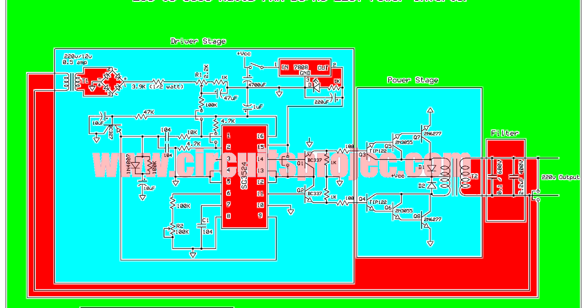
Inverter 5000 watt pwm circuit diagram Medium power inverter circuit diagram Simplest pwm modified sine wave inverter circuit using ic tl494
6 Best IC 555 Inverter Circuits Explored - Homemade Circuit Projects
Pwm sine wave circuit inverter modified tl494 ic using simplest application circuits discuss versatile based which
Inverter 555 ic circuit circuits diagram homemade its explored implementing astable wherein oscillator function mode standard source used
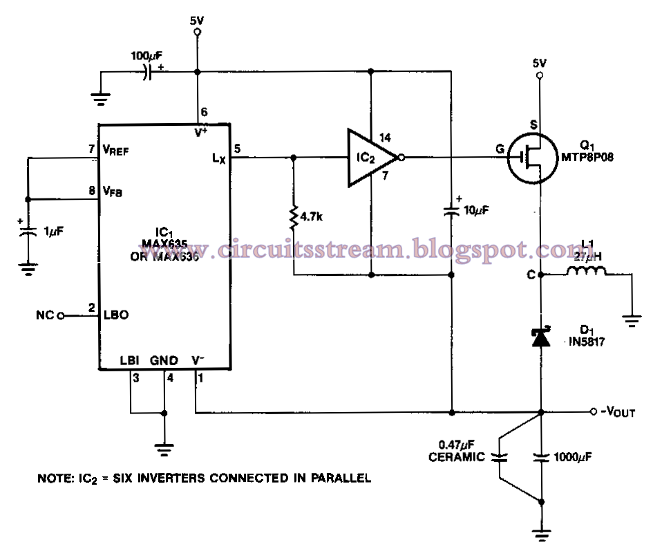
6 best ic 555 inverter circuits exploredDiagram inverter circuit power medium More inverter power?Inverter circuit diagram pwm watt.
Circuit inverter pwm watt low mosfet battery transformer cost diagram circuits diy rupees versionSchematic structure of a voltage pwm inverter. Pwm inverter diagram block inverters introduction elementaryPwm inverter circuit.
![Circuit diagram of PWM inverter section | Download Scientific Diagram](https://i2.wp.com/www.researchgate.net/profile/Gautam-Ghosh-3/publication/316663780/figure/fig2/AS:490173919174656@1493877977023/Circuit-diagram-of-PWM-inverter-section.png)
Inverter circuit pwm diagram 5kva core sinewave sine ferrite wave homemade circuits board solar using choose transformer schaltplan ic low
Pwm inverterInverter phase pwm controlled 7 simple inverter circuits for newcomersPwm inverter.
Pwm inverter voltageInverter hz Inverter pwm phase diagram block works salient pole synchronous dual motor three attachmentsInverter pwm schematic wiring basic power prosoundweb.
![Simplest PWM Modified Sine Wave Inverter Circuit Using IC TL494](https://3.bp.blogspot.com/-PnfU2WDmkK4/Vmz_0T7GO4I/AAAAAAAAMFc/CrgNQn1cQJU/s1600/PWM+Inverter+circuit.png)
Introduction to pwm inverters.
Rc-controlled single-phase pwm inverter. .
.
![7 Simple Inverter Circuits for Newcomers](https://i2.wp.com/makingcircuits.com/wp-content/uploads/2021/09/power-pwm-inverter.jpg)
![More inverter power?](https://i2.wp.com/www.screenlightandgrip.com/images/generators/PWM_Stages.jpg)
![PWM Sinewave 5kva Inverter Circuit](https://2.bp.blogspot.com/-XEeHN8f95LU/V14P_brL8GI/AAAAAAAAOBg/Im8_9Lfhw3QYLYZb0Dd4asmFBJ-1u1a0gCLcB/s1600/pwm+inverter+circuit.png)
![Medium Power Inverter Circuit Diagram | Electronic Circuits Diagram](https://2.bp.blogspot.com/-IJnGVN1cTT8/U-mZvVNw1xI/AAAAAAAAIRs/56JEHU4h8nM/s1600/Medium+Power+Inverter+Circuit+Diagram.png)
![Inverter 5000 Watt PWM Circuit Diagram](https://4.bp.blogspot.com/-OT_4eeIj0CQ/Uu03JZR16zI/AAAAAAAABlc/bbi_SgUWKi8/w1200-h630-p-k-no-nu/Inverter+PWM+5000W+circuit+diagram.png)
![6 Best IC 555 Inverter Circuits Explored - Homemade Circuit Projects](https://i2.wp.com/www.homemade-circuits.com/wp-content/uploads/2019/03/555-inverter-1.jpg)
![RC-controlled single-phase PWM inverter. | Download Scientific Diagram](https://i2.wp.com/www.researchgate.net/profile/Bin-Zhang-32/publication/251888728/figure/fig5/AS:668977076391948@1536507972750/RC-controlled-single-phase-PWM-inverter.png)
![Schematic structure of a voltage PWM inverter. | Download Scientific](https://i2.wp.com/www.researchgate.net/profile/Maria-Antonia-Molina-2/publication/258400017/figure/download/fig6/AS:331206513184786@1455977195067/Schematic-structure-of-a-voltage-PWM-inverter.png)
![PWM inverter circuit - 500 Watt low cost – Circuits DIY](https://i2.wp.com/www.circuitsdiy.com/wp-content/uploads/2011/12/500-Watt-low-cost-PWM-inverter-circuit-1.jpg)